Special electronic circuitries were invented in the 1950s and 60s for the creation of ultrasound B scans
The follwing from Thomas Brown on his earlier scanners:"For the technobuffs, the electronic system, though it was novel, had the virtue of great simplicity. It consisted, in essence, of two vacuum-tube integrator and mixer circuits, acting as vertical and horizontal timebase generators.
The vector sum of these timebases, as seen on the display, was a linear timebase vector, starting at a position on the screen corresponding to the position of the probe spindle, and moving in a direction corresponding to the direction of propagation of sound into the patient. When the timebase got to a position corresponding to the position of the probe face (with corrections because of the type of "Perspex" fronting blocks used), the transmitter was fired. As echoes came back they were amplified in the MKIV, and then passed to a rather unusual signal processor - where art and science tended to co-exist - and then used to brightness-modulate the timebase............... .In the early days Kelvin & Hughes tended to use separate transmit and receive systems, with double-transducer probes. The advantages of this are often misunderstood.
The first is that the sensitive receiver amplifier is not 'assaulted' by the massive transmission pulse, and is therefore in a position to handle small echo returns from sources close to the probe face. Secondly, the two acoustic systems are side-by-side, so that their acoustic beam patterns progressively overlap with distance from the probe. This means that the combined sensitivity is low close to the probe face, rising to a maximum at some centimetres away. It was this characteristic which explains why swept gain ("TVG") was not high on our list of early priorities. We could get the effect of TVG simply by adjustment of the probe system geometry. There was a significant penalty in overall sensitivity, but with the poor performance of the available single-transducer probes of the day, this was offset by the other advantages. Initially quartz was used as a transducer, subsequently replaced by barium titanate........
The frequency used was 2.5 MHz, corresponding to an ultrasonic wavelength of 0.6mm This was chosen partly because it was one of the standard frequencies on the Kelvin & Hughes industrial machines, and partly because it was quickly found to give a good trade-off between range and resolution, with the available technology of the day. Patents were applied for by Kelvin & Hughes prior to publication of our early results in 'Lancet' in June 1958. I was named as inventor, though commercial rights were assigned to the company. I understand that this patent, and it's foreign cases, are regarded as being extremely basic, and cover all subsequent contact scanners. However, Kelvin & Hughes were locked in a patent battle with Automation Industries, and no attempt was made to enforce these patents until they were eventually acquired by Automation about 1965..............." .Later on, stiill more sophisticated circuitries were invented in the 1960s for the creation of ultrasound B scans:

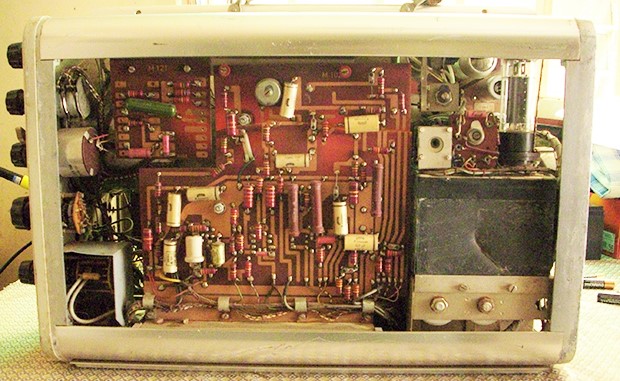
Early scanner circuitry from Siemens, Germany.
The scan converter tube is at the right upper corner.

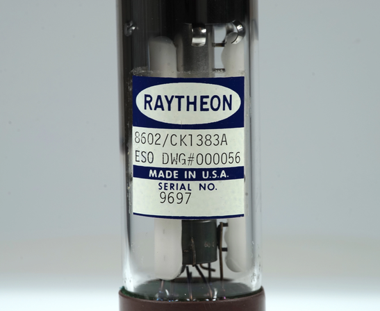
The Raytheon scan convertor tube
1. Pulse echo operation:Ultrasound is produced using devices called transducers. These devices use piezoelectric crystals, in which a varying voltage causes a correspondingly varying strain. By varying the input voltage at a suitably high rate, ultrasound waves are produced. Similarly, by varying the strain on the piezoelectric crystal, a correspondingly varying voltage is produced. Since these processes are reversible, the same device can be used to both transmit and detect the waves. This greatly simplifies the design.

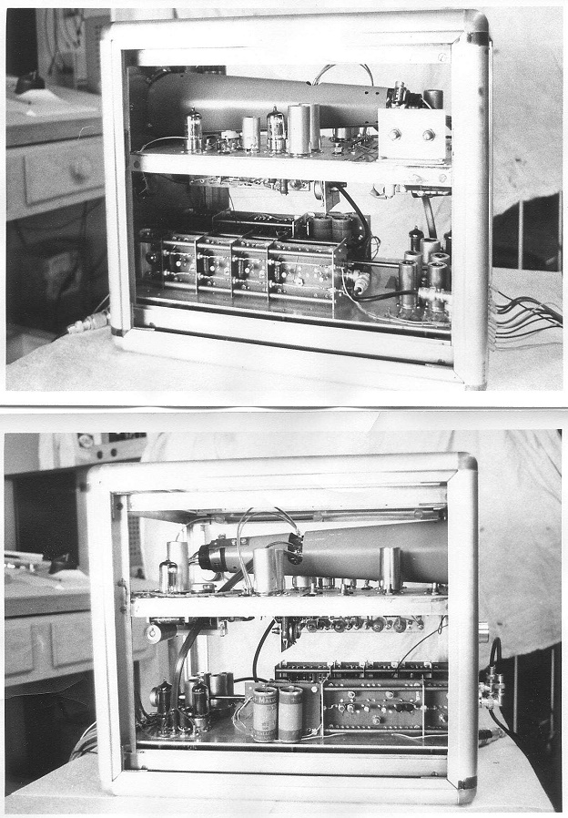
Inside of the electronics console. Vacumn tubes were used instead of transisters.
The transmitter circuit produces a high-amplitude, short duration pulse. The output control then attenuates the amplitude of the shock pulse, before applying it to the transducer. Ultrasound is not emitted continuously from the transducer, as that would make echo-detection useless. There would be no way of knowing how long a wave had been travelling once it returned to the transducer. Instead, transducers oscillate between two modes. First a pulse of ultrasound is emitted, and then in the pause that follows the time that elapses for the echos to be detected is measured. The distance can then be calculated basing on specific equation and governs the travel of sound waves in tissues. The intensity of the echos is also recorded, and is used when rendering the scans.2. The Limiter circuitry:
The Limiter circuitry protects the rest of the receiver from the high-transmitter voltages. Because both the transmitter and the receiver are connected to the transducer, the transmitter is connected directly into the receiver. If the high-transmission voltages were to enter the receiver unattenuated, it would saturate the receiver for a relatively long period of time, obscuring all shallow echoes. The limiter circuit allowed low-amplitude signals (echoes) to pass unaffected but in order to protect the receiver, it limits or clips any high-amplitude signal that is above a predetermined threshold.
3. The receiver circuitry:
After each transmission pulse the transducer then receives its returning echoes. After the received echoes are converted into weak voltage waveforms by the transducer, they are processed by the receiver. The receiver is actually made up of several sub-circuits, each one performing a specific signal processing function.
a. The log amplifiercircuitry amplifies the weak echo signals by over 100 dB.
b. the rectifier circuitry, where the negative half-cycles in the echo voltage waveforms are converted into positive half-cycles.
c. the demodulation circuitry, where the fundamental frequency signal on which the echo amplitude information has been carried would be eliminated, leaving only the so-called envelope (i.e., magnitude) of the echo signal.
d. The time gain compensation circuitry.
The output of the demodulator is the amplitude of the echo signal and its time delay from the transmission pulse. Homogeneous soft tissues in the body should appear uniform in the ultrasonic image. However, echo amplitudes received from deeper soft tissue structures have lower amplitudes because of the attenuation of the overlying tissue. This leads to a graded appearance of the tissue gray-scale image. This problem is solved by a method called time gain compensation. This is a method of time-increasing the gain of the log amplifier, in sync with the arrival of lower and lower amplitude echoes from deeper and deeper in the body. The voltage that controls the gain of the log amplifier is usually varied linearly with an operator selectable slope. Thus, by proper selection of the operator selectable slope of the swept gain, the effects of tissue attenuation in the image may be compensated. Time gain compensation was supposed to be invented by John Reid in working with John Wild in the early 1950s.
Back to History of Ultrasound in Obstetrics and Gynecology.